I recently made a small lab that was useful for testing / simulating multiple VoIP telephones with PCs sat behind them using Cisco Packet Tracer. Below is how i completed this:
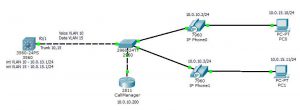
3560 / Router:
– I decided to use a 3560 (Layer 3 Switch) but this could be a Router.
Create VLANS and create Trunk port:
vlan 10
 name Voice
vlan 15
 name Data
!
interface Vlan10
 ip address 10.0.10.1 255.255.255.0
!
interface Vlan15
 ip address 10.0.15.1 255.255.255.0
!
interface FastEthernet0/1
 switchport trunk allowed vlan 10,15
 switchport trunk encapsulation dot1q
 switchport mode trunk
 duplex full
!
Create DHCP Scope:
ip dhcp pool VOICE
 network 10.0.10.0 255.255.255.0
 default-router 10.0.10.1
 option 150 ip 10.0.10.200
In the above DHCP Scope we create a scope and set option 150, the IP address for this 10.0.10.200 will show later but this is the IP address of where ever the Call Manager functionality is located, this would normally be a Phone System / PBX but we will later use a 2811 Router for this traffic.
2960 / Switch
Create VLANS and Trunk Port:
vlan 10
 name Voice
vlan 15
 name Data
interface FastEthernet0/1
 switchport trunk allowed vlan 10,15
 switchport mode trunk
 duplex full
!
Configure Phone Ports:
interface FastEthernet0/2
 switchport access vlan 15
 switchport mode access
 switchport nonegotiate
 switchport voice vlan 10
 spanning-tree portfast
!
interface FastEthernet0/3
 switchport access vlan 15
 switchport mode access
 switchport nonegotiate
 switchport voice vlan 10
 spanning-tree portfast
!
Configuring IP Phone
The IP Phones have a couple of ports on the back of them and allow to do pass through and connect a PC on the back of them, when connecting up ensure that the Switch port is connected to the Switch and PC port is connected to PC.
These phones can be setup so that they are powered by using power over Ethernet and get the power from the switches,

The phone will now connect and on the GUI Screen you will get this screen, this shows that is picking up an IP Address from the DHCP Scope we created earlier.

Once it has an IP Address you need to configure a Call Manager to act as the Phone System.
Configuring Call Manager Router
In this setup I have set this as a seperate device but this can be added to the primary Router if needed (You’ll just have to change the Option 150 IP Address in the DCHP Config on the 3560 / Router).
interface FastEthernet0/0
 ip address 10.0.10.200 255.255.255.0
 duplex full
 speed auto
!
telephony-service
 max-ephones 5
 max-dn 5
 ip source-address 10.0.10.200 port 2000
 auto assign 4 to 6
 auto assign 1 to 5
!
ephone-dn 1
 number 54001
!
ephone-dn 2
 number 54002
!
Once this configuration is in place the IP Phone should now connect, you will notice that in the top right hand side of the simulated LCD Display it shows the DN Number of 54001 as created above.

Configuring PCs
The IP Phones will pick up their IP Addresses from the DHCP Scope we created on the 3560 / Router but the PCs we will have to set them statically, set the IP addresses to anything within the 10.0.15.0/24 subnet (below is an example) also set the Default gateway to 10.0.15.1
PC0:
IP Address:      10.0.15.10Subnet Mask:     255.255.255.0Default Gateway: 10.0.15.1

PC1:
IP Address:      10.0.15.11
Subnet Mask:     255.255.255.0
Default Gateway: 10.0.15.1
Testing Connectivity
To test connectivit, ensure that PC0 and PC1 can both ping the Default Gateway 10.0.15.1
Test connectivity by ensuring can ping from PC0 to PC1.
Test inter-vlan routing by from PC0 and PC1 ping the Default Gateway of Telephony VLAN 10.0.10.1.
Testing Voice Calls
Once the above has been completed you can from Cisco Packet Tracer simulate a telephone call through the IP Phones, to do this in packet tracer open up both phones.

On one phone click on the handset to pick up the phone, then using the key pad dial the DN number of the other handset (in the example below 54002 – this is shown in the top right hand side of the LCD Display of the handset).

This will then ring the phone on the right, you can see the call on the LCD display also the light on the handset will flash.
